Polarisers are optical components which convert unpolarised radiation into orthogonal linearly polarised components.
We offer two distinct devices for operation throughout the millimetre and far infrared spectral region and at both ambient and cryogenic temperatures.
Wire grid polarisers are suitable at frequencies below 3 THz; wire is wound across a supporting metal frame and then glued into place. Wire diameters as low as 5 um are available, and we recommend this relatively low-cost option for frequencies up to 3 THz. Diameters up to 500 mm are possible. More information can be found below.
At higher frequencies wire grid polarisers become less efficient. For these frequencies we offer lithographic polarisers in which thin metal patterns are deposited onto ultra-thin polymeric substrates. Pattern repeat distances of 2um and 10um are standards and these are available in diameters up to approximately 200 mm. See below for further details.
Wire grid polarisers
| Operating Temperature | Ambient (Code QWG/RT) Cryogenic (Code QWG/C) |
| Frequency range | <= 3THz |
| Maximum size | 500 mm |
| Wire | Tungsten or Gold-plated Tungsten |
| Wire diameter | >= 5 um |
| Wire separation | >= 10 um |
|
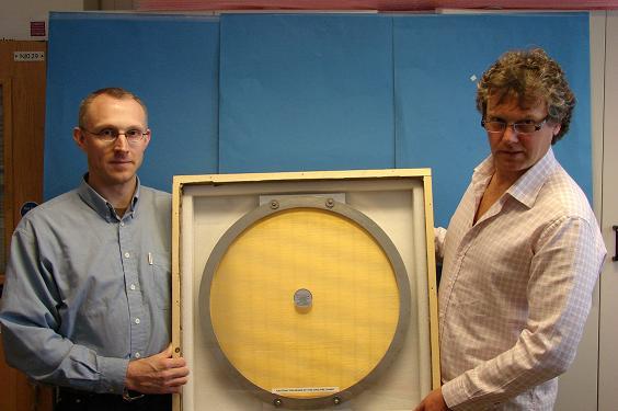
Wire grid polarisers are offered using wire diameters from 5 um upwards. Our computer-controlled grid-winding machine weighs more than one tonne and is capable of winding grids up to 500 mm in diameter. The photograph shows one of the larger wire grid polarisers we have made to date – the winding of a pair like this used more than 6km of wire. Wire is wound across a supporting metal frame and then glued in place (often sandwiched between two frame halves).
|
We are happy to consider your own support frame design requirements at up to 500 mm in diameter, and our engineers will be happy to discuss mounting and positioning attachments.
Polarisers of this kind can operate at ambient temperatures (Product Code QWG/RT) or at cryogenic temperatures (Product Code QWG/C) if required.
We can wind wires on to grids that you supply; or clean and rewire an existing polariser.
It is very important to cut polariser frames without adding mechanical stresses and the non-contact spark erosion process (we use a Swiss AGIE spark erosion machine) is in our view, the best way to do this. The frames are then ground flat using a large surface grinder.
The photograph below shows a wire polariser used to remove any residual cross-polar signal emitted by a horn antenna.

A recent innovation is the manufacture of crossed wire grids, based on an idea by John Payne at NRAO (Tucson). Crossed grids allow an un-polarised beam to be separated into orthogonal components with both beams being deflected by 90 degrees. Compact quasi-optical systems including Martin-Puplett diplexers can be built up in this way. A further advantage of this novel arrangement is that unwanted higher frequency radiation passes directly through the crossed grid and thus is not directed toward the detectors. This can be very useful in reducing the loading on cryostat cold plates.
The photograph below is of such a crossed grid manufactured for Max Planck Institute (Bonn). This grid forms part of a dual polarization detector designed and built for the Smithsonian Astrophysical Observatory in Cambridge, MA (USA.)

Photolithographic Polarisers
Our photolithographic polarisers are designed for the higher frequency range (i.e. above 3 THz) where free-standing polarisers become less efficient. They are commonly used in polarising FT spectrometers for the far infrared region and in polarisation sensitive receivers such as the higher frequency bands of ALMA. They have also been qualified for use in long-life space-borne projects such as Cassini.
A pattern of thin parallel lines is created in metal on the surface of an ultra-thin polymeric substrate. As a consequence of their structure and of the method used to construct them, these polarisers must be circular and are usually mounted in stainless steel support frames.
The support substrate is usually 0.9 um or 1.5 um thick Mylar, and the metal 'wires' are copper or gold.
The polarisers are mounted in their support frames by means of a press, and each frame design requires pressing tools. We therefore offer a range of standard polariser support frame sizes. Special sizes, up to the maxima indicated in the table below, are still available but costs will include the manufacture of special press tools.
We have a range of patterns available with dimensions as follows:
| Product Code | Line Width | Line Spacing | Maximum Diameter |
|
P2 |
1 um |
2 um |
300 mm |
Edited May11